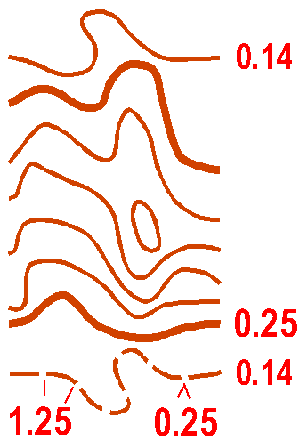
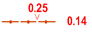
A line joining points of equal height. The standard vertical interval between contours is 5 metres. The smallest bend in a contour is 0.25 mm from centre to centre of the lines.
Colour: brown.
102 Index contour
Every fifth contour shall be drawn with a thicker line. This is an aid to the quick assessment of height difference and the overall shape of the terrain surface. Where an index contour coincides with an area of much detail, it may be shown with a normal contour line.
Colour: brown.
103 Form line
An intermediate contour line. Form lines are used where more information can be given about the shape of the ground. They are used only where representation is not possible with ordinary contours. Only one form line may be used between neighbouring contours.
Colour: brown.

Slope lines may be drawn on the lower side of a contour line, e.g. along the line of a re-entrant or in a depression. They are used only where it is necessary to clarify the direction of slope.
Colour: brown.
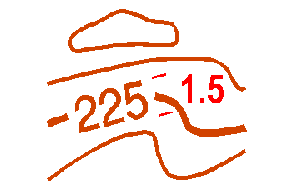
Contour values may be included to aid assessment of large height differences. They are inserted in the index contours in positions where other detail is not obscured. The figures should be orientated so that the top of the figure is on the higher side of the contour.
Colour: brown.
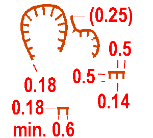
A steep earth bank is an abrupt change in ground level which can be clearly distinguished from its surroundings, e.g. gravel or sand pits, road and railway cuttings or embankments. The tags should show the full extent of the slope, but may be omitted if two banks are close together. Impassable banks should be drawn with symbol 201 (impassable cliff). The line width of very high earth banks may be 0.25 mm.
Colour: brown.
Distinct earth wall. Minimum height is 1 m.
Colour: brown.
A small or partly ruined earth wall shall be shown with a dashed line. Minimum height is 0.5 m.
Colour: brown.
An erosion gully or trench which is too small to be shown by symbol 106 is shown by a single line. The line width reflects the size of the gully. Minimum depth 1 m. The end of the line is pointed.
Colour: brown.
A small erosion gully or trench. Minimum depth 0.5 m.
Colour: brown.

Knolls are shown with contour lines. A prominent knoll falling between contour lines may still be represented by a contour line if the deviation from the actual contour level is less than 25%. Smaller or flatter knolls should be shown with form lines.
Colour: brown.

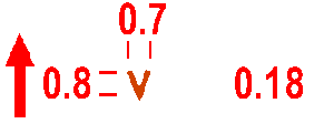
A small obvious mound or rocky knoll which cannot be drawn to scale with a contour (diameter of mound less than ca. 5 m). The height of the knoll should be a minimum of 1 m from the surrounding ground. The symbol may not touch a contour line.
Colour: brown.

A small obvious elongated knoll which cannot be drawn to scale with a contour (length less than 12 m and width less than 4 m). The height of the knoll should be a minimum of 1 m from the surrounding ground. Knolls larger than this must be shown by contours. The symbol may not be drawn in free form or such that two elongated knoll symbols overlap. The symbol may not touch a contour line.
Colour: brown.

Depressions are shown with contours or form lines and slope lines. Prominent depressions falling between contour lines may be represented by a contour line if the deviation from the actual contour level is less than 25%. Smaller or shallower depressions should be shown by form lines.
Colour: brown.
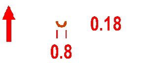
Small shallow natural depressions and hollows (minimum diameter 2 m) which cannot be shown to scale by contours are represented by a semicircle. Minimum depth from the surrounding ground should be 1 m. Location is the centre of gravity of the symbol, which is orientated to north. Symbol 116 is used for man-made pits.
Colour: brown.
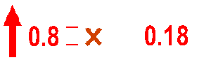
Pits and holes with distinct steep sides which cannot be shown to scale by symbol 106 (minimum diameter 2 m). Minimum depth from the surrounding ground should be 1 m. Location is the centre of gravity of the symbol which is orientated to north.
Colour: brown.
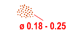
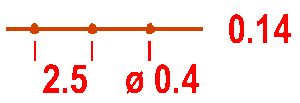
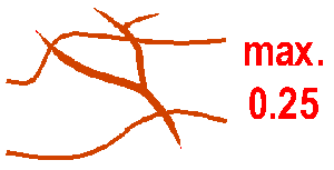
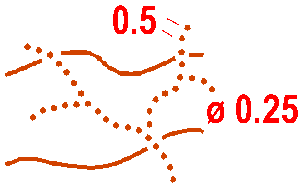
An area of pits or knolls which is too intricate to be shown in detail. The density of randomly placed dots may vary according to the detail on the ground.
Colour: brown.
This symbol can be used for a special small land form feature. The definition of the symbol must be given in the map legend.
Colour: brown.


