|
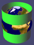
A cylindrical projection can be imagined in its simplest form as a cylinder that has been wrapped around a globe at the equator. The points on the spherical grid are transferred to the cylinder which is then unfolded into a flat plane. The equator is the "normal aspect" or viewpoint for these projections. This family of projections are typically used to represent the entire world. When projected from the centre of the globe with the normal aspect, the typical grid appearance for cylindrical projections shows parallels and meridians forming straight perpendicular lines. The spacing varies depending on the type of cylindrical projection. |
 |
Equirectangular projection
|
 |
Mercator projection
|
 |
Lambert's cylindrical equal-area projection
|
 |
Gall's stereographic cylindrical projection
|
Oblique Mercator
Oblique Mercator projections are used to portray regions along great circles. Distances are true along a great circle defined by the tangent line formed by the sphere and the oblique cylinder, elsewhere distance, shape, and areas are distorted. Once used to map Landsat images (now replaced by the Space Oblique Mercator), this projection is used for areas that are long, thin zones at a diagonal with respect to north, such as Alaska State Plane Zones.
Transverse Mercator
Transverse Mercator projections result from projecting the sphere onto a cylinder tangent to a central meridian. Transverse Mercator maps are often used to portray areas with larger north-south than east-west extent. Distortion of scale, distance, direction and area increase away from the central meridian. Many national grid systems are based on the Transverse Mercator projection, such as the British National Grid (BNG).
Universal Transverse Mercator
The UTM projection is used to define horizontal, positions world-wide by dividing the surface of the Earth into 6 degree zones, each mapped by the Transverse Mercator projection with a central meridian in the center of the zone. UTM zone numbers similarly to the Gauss-Krüger (GK) projection numbers designate 6 degree longitudinal strips extending from 80 degrees South latitude to 84 degrees North latitude. UTM zone characters designate 8 degree (4 degree in GK) zones extending north and south from the equator. UTM zone eastings are measured from the central meridian (with a 500km false easting to insure positive coordinates). Northings are measured from the equator (with a 10,000km false northing for positions south of the equator).